Design and Operation of a Basic Waveform Generator Circuit

PRN: 202401070154
Introduction

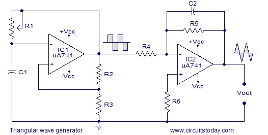
Basic block diagram showing oscillator, comparator, and wave-shaping stages.
1. The Core Idea: Oscillation from RC Networks
At its heart, the waveform generator is an
oscillator — it turns a steady DC voltage into a repeating AC waveform. The
simplest version uses a resistor (R) and capacitor (C) to set the rhythm of
oscillation. The capacitor charges and discharges through the resistor,
creating a repeating voltage pattern.

Voltage across the capacitor during
charging:
Vc(t) = Vmax(1 - e^(-t/RC))
During discharge:
Vc(t) = Vmax * e^(-t/RC)
The time constant (τ = RC) defines how
quickly this happens. If a comparator toggles at two voltage thresholds, the
capacitor alternates charging and discharging — forming a continuous waveform.
Approximate frequency of oscillation:
f = 1 / (2RC * ln((1 + β) / (1 - β)))
2. Triangle and Square Waves
When the capacitor charges linearly using a
constant current source instead of a resistor, it forms a triangle wave:
Vc(t) = (I / C) * t
When the voltage hits an upper threshold
(+VT), a comparator flips the current direction — discharging it until (−VT),
then back again. The frequency of the triangle wave is given by:
f = I / (4CVT)
The comparator output itself is a square
wave, switching high and low in sync with the triangle’s rise and fall.
3. The Sine Wave: From Triangle to Curve
The sine wave is created by shaping the
triangle wave through a diode–resistor network. This network compresses the
linear slopes near the peaks, bending them into a smooth sine-like curve:
Vout ≈ A * sin⁻¹(Vin / B)
4. Frequency and Amplitude Control
• Frequency knob: a potentiometer that
changes the resistance or current, directly tuning frequency (f ∝ 1/RC).
• Amplitude knob: acts as a voltage divider, scaling the output signal’s
voltage level.
5. Why It Matters
The waveform generator embodies several
fundamental principles:
• RC oscillation — the basis of timing and signal generation.
• Comparators and current sources — how analog circuits make decisions.
• Wave shaping — how electronics turn straight lines into curves.
Every time you connect a signal generator, remember it’s not just a box — it’s
a precise balance of charge, timing, and analog mathematics.
References
1. XR2206 Monolithic Function Generator
Datasheet, Exar Corporation.
2. Sedra & Smith, Microelectronic
Circuits, 8th Edition, Oxford University Press, 2019.
3. Horowitz, P. & Hill, W., The Art of
Electronics, 3rd Edition, Cambridge University Press, 2015.
4. Texas Instruments, “Function Generator
Fundamentals,” Application Note (TI AN-263).
Comments
Post a Comment